Marine Radio – Main transmitter Standard Radio ST1200
Dear Sparks,
following article by Technical Journalist Dr. Marcin Marciniak – SP5XMI
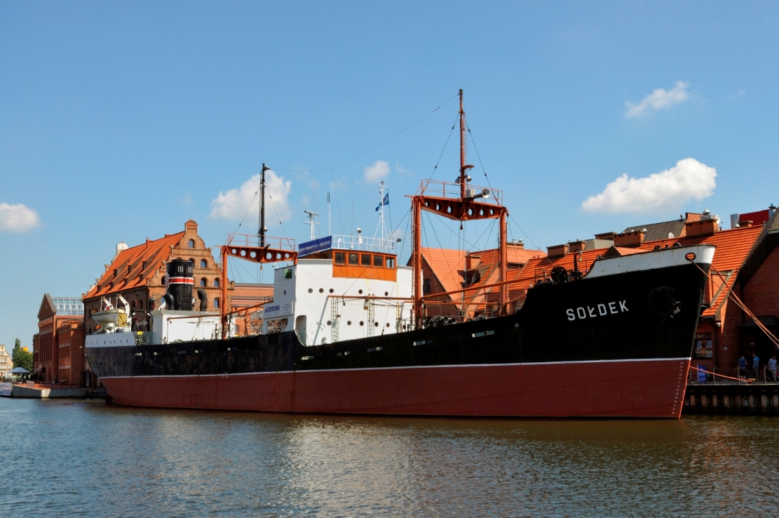
This masterpiece of old tube technology is quite rare comparing to Marconi, Mackay or even Dansk Radio (the Elektromekano brand). It came from a Swedish company „Standard Radio & Telefon AB” in the 50s, it was installed on three Polish vessels including s/s SOŁDEK callsign SPCJ (https://en.wikipedia.org/wiki/SS_So%C5%82dek), now a museum ship. You can see this ship as a part of National Maritime Museum in Gdańsk, Poland. Unfortunately none of the original radio sets onboard are in working condition. A group of enthusiasts wanted to restore main transmitter and one of the receivers but the process is very complicated as of now.
There were also three sister ships that had similar radio setup: s/s BRYGADA MAKOWSKIEGO/SPCN (written off in 1979) and s/s JEDNOSC ROBOTNICZA/SPCK (written off in 1978). It’s Standard Radio ST1200 *) that covers maritime bands 4-6-8-12MHz (A1/A2), telegraphy on whole 500kHz band and AM coastal telephony on 1,8MHz band. Therefore its range and modes were more than adequate for voyages all over Baltic Sea or the English Channel. This is where s/s SOŁDEK sailed.
It’s comprised of separate modules: exciter and final stage of HF CW transmitter, MF AM coastal telephone transmitter, 500kc main transmitter, power supply and A2/A3 modulator for W/T and R/T. It uses standard chain on HF W/T: crystal oscillator, frequency doubler/tripler chain, separator, driver and C-class power amplifier. One stage of the doublers is bypassed on lower bands. MF R/T is also crystal controlled, uses standard principle with Class-C PA, anode modulated. The 500kc main transmitter uses free running oscillator. The HT is in the kilovolt range. Power supply requires AC converter (a dynamotor perhaps) and separate voltage regulator because many vessels of that time used DC power supply. The s/s SOŁDEK/SPCJ was no exception – it was a DC ship.

The radio room of s/s SOŁDEK/SPCJ
not to be confused with ITT ST1200, the American one works SSB, this one comes from the 50s and is only CW and AM.

Two racks of the main transmitter. On the left-hand side: local power supply and modulator for A2 mode, exciter and driver and the finals. On the right-hand side: power supply and charging panel, AM radiotelephone transmitter for medium wave and main 500kHz CW transmitter.

Main transmitter for 500kc band. Uses free running oscillator with a tuning lock knob. This transmitter uses oscillator, separator and C-Class power amplifier. Tuning switch enables transmitter on low power settings.

Exciter of the shortwave W/T transmitter. It’s crystal controlled – 6 pcs of 2MHz crystals can be used (on SPCJ only three of them were inserted). Frequencies used: 4178, 4201, 4222 ; 6268.5, 6301.5 , 6333; 8358, 8402, 8444 and 12537, 12603. Third crystal on 12MHz after doubling and tripling was 12666 MHz therefore outside of the usable 12Mc maritime band in Poland.
Signal from oscillator is fed into the doubler that works also as a tripler for 6MHz band. Changing the band swich position bypasses one of the doublers in chain. It’s similar to the doubler/tripler chain used in Marconi Oceanspan transmitter. Then the driver stage is tuned to resonance. All voltages and currents can be measured using a selectable meter. Cathode current of the last driver stage is measured by a separate meter. Tuning procedure: set a proper crystal to be used, set the band switch to position depending on the band and tune doubler to resonance within band (cathode meter should deflect some, tune for maximum deflection). Then tune final stage, then tune the driver stage to maximum deflection and correct doubler tuning if needed. Take care of maximum reading of anode current in the final stage.

Final stage of W/T shortwave transmitter. Tx uses direct heated tubes in parallel working in class C. Final stage tuning is typical – set the band switch to proper position and then tune the output tank for maximum aerial current. Correct final drive by driver tuning if needed.

This is the transmitter for R/T on medium wave (1,8MHz). It is also crystal controlled, tuning is similar to W/T module. Besides crystals that are installed inside, there is a socket for external crystal. Frequencies used: 1960, 2049, 2056, 2090, 2107, 2182 and additionally external crystals: 2411, 3331. All in AM of course.

Power supply, modulator and mode selector for W/T. Power switch enabled filaments (“START”), enabled screen and HT but with lowered voltage (“TUNE”) and finally full HT voltage (“SEND”). A2 mode enabled oscillator for A2 W/T mode.

Main power supply panel – the input voltage after rotary DC/AC converter (s/s SOŁDEK/SPCJ was a DC ship) was fed into a voltage regulator for stabilizing input voltage. All voltages (mains, battery, bias, HT and battery charging) could be measured by selectable meter.
Yours,
Marcin